The Unboxing…
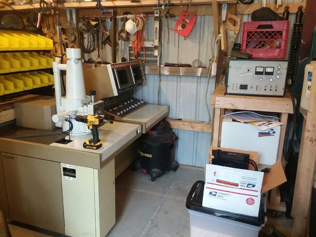
Recently I acquired a Jeol JSM-300T Scanning Electron Microscope. There are some videos on the set up and repair of this scope on the YouTube channel (or will be soon!). I wanted to go into as much detail about the scope, how it works, what it does, how to repair, how to wire and how to use it. The catch with these scopes is that they were not really intended to be installed by the customer (as far as I can tell), or if they were that customer would be the facilities tech department. Either way the documentation, as far as I can tell, that comes with the SEM is meant for basic maintenance and operation of the device. Installing it is not in the basic manual. I was lucky and received the schematic book with the SEM, the schematics are for the 220T and 330T but it seems that the 300T is very similar to both of these models and in some cases a combination of them. I hope the following project page will be helpful for anyone else who may be considering buying a Jeol SEM or possibly want to try building their own version.

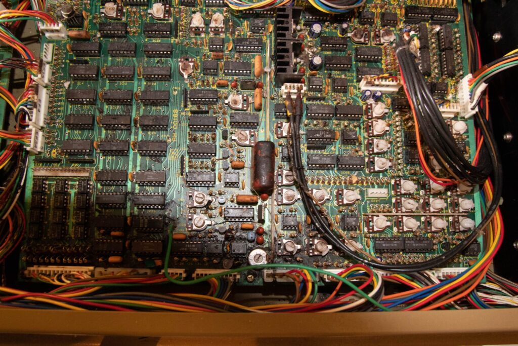
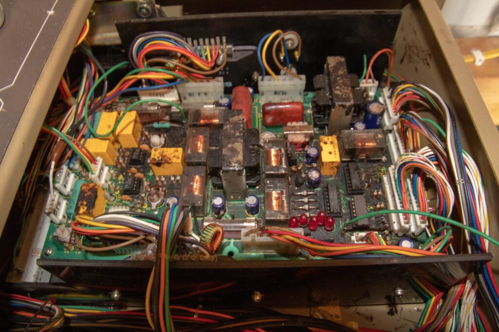
I found this scope on eBay for a pretty good deal, so I rented a trailer and went up to New York. The Combined weight for the scope is somewhere around 800 pounds, so moving on and off the trailer is not an easy task. The 300T came with extra filaments, apertures, filament holder (I suspect this is a damaged part) and a bunch of Polaroid film for the Polaroid camera… did I mention I want to digitize the output? First things first, I started by removing the panels to find the wires that connect the consoles. In doing so I found that some mice have made the scanning control boards and the imaging CRT home. After cleaning the nest material off it was clear that the excrement had caused some damage to the PCBs. After significant cleaning it turns out the that the boards are all in good condition and none of the traces are damaged (as far as I can tell). The only damage was a wire that lost its insulation, easy fix!


The next job is to identify the loose wires and find the correct connectors in each unit. All of the standard style connectors are labeled so its simply a matter of matching the designation with the correct socket on the board. For example HJ9 (in the image above) is plugged into the number 9 socket on the board labeled HJ (EOS Drive Board). There are a few wires on either part that are not labeled. A few are green and can be assumed that they are ground (these will be traced out to confirm). Another has a clear case with a fairly heavy gauge wire. This is most likely a high voltage wire and can be traced in the schematics and on the machine to confirm. Below is a table of each connector (in no particular order) on each piece of the scope in case anyone is playing along at home.


Leave a Reply